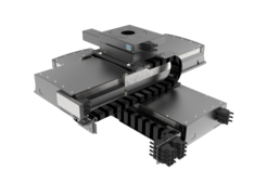
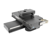
PLT320-DLM
Linear Stages
Heavy duty linear stage (linear motor), travel 300 - 1500 mm, rep ± 0.4 µm, load 25 kg, speed 2445 mm/s

Precision in heavy-duty operation
The PLT320-DLM is the model of choice for positioning heavy loads with speed and precision. The integrated linear motor, in combination with a linear measuring system, can accelerate heavy loads with extreme precision.
Basis for multi-axis systems
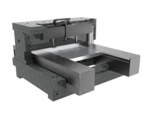
With a width of 320 mm, this linear stage is the largest model in the PLT series. It can be used as the base axis in multi-axis systems for very high loads, but is also suitable as a single axis. With travel distances ranging from 300 mm to 1000 mm, the PLT320 offers a number of options for addressing a range of applications.
Designed for industrial environments
In common with all the stages in the PLT series, the PLT320 is suitably protected for use in industrial environments. It is characterized by a robust casing and solid drive concept.
| PLT320 | -300-DLM-L | -400-DLM-L | -500-DLM-L | -750-DLM-L | -1000-DLM-L | -1500-DLM-L | |
| Travel | [mm] | 300 | 400 | 500 | 750 | 1000 | 1500 |
| Repeatability unidirectional | [μm] | ± 0.4 | ± 0.4 | ± 0.4 | ± 0.4 | ± 0.4 | ± 0.4 |
| Repeatability bidirectional | [μm] | ± 0.5 | ± 0.5 | ± 0.5 | ± 0.5 | ± 0.5 | ± 0.5 |
| Accuracy | [μm] | ± 2.3 | ± 2.6 | ± 2.9 | ± 3.6 | ± 4.2 | ± 5.4 |
| Flatness | [μm] | ± 9 | ± 12 | ± 15 | ± 25 | ± 30 | ± 50 |
| Straightness | [μm] | ± 4.5 | ± 6 | ± 7.5 | ± 11 | ± 15 | ± 25 |
| Positioning speed | [mm/s] | 620 | 700 | 790 | 1000 | 1210 | 1630 |
| Max. Speed | [mm/s] | 930 | 1050 | 1185 | 1500 | 1815 | 2445 |
| Max. acceleration | [m/s2] | 12 | 14 | 16 | 20 | 25 | 35 |
| Max. load Fx | [N] | 250 | 250 | 250 | 250 | 250 | 250 |
| Max. load Fy | [N] | 3100 | 3100 | 3100 | 3100 | 3100 | 3100 |
| Max. load Fz | [N] | 3100 | 3100 | 3100 | 3100 | 3100 | 3100 |
| Max. torque Mx | [Nm] | 110 | 110 | 110 | 110 | 110 | 110 |
| Max. torque My | [Nm] | 150 | 150 | 150 | 150 | 150 | 150 |
| Max. torque Mz | [Nm] | 150 | 150 | 150 | 150 | 150 | 150 |
| Pitch | [µrad] | ± 35 | ± 40 | ± 45 | ± 55 | ± 65 | ± 75 |
| Yaw | [µrad] | ± 17 | ± 20 | ± 20 | ± 25 | ± 30 | ± 40 |
| Resolution | [µm] | 0.1 | 0.1 | 0.1 | 0.1 | 0.1 | 0.1 |
| Weight | [kg] | 49 | 56 | 64 | |||
| L1 | [mm] | 810 | 910 | 1010 | 1260 | 1510 |
Related Products


Almost all atmospheric standard stages are unanodized with UHV lubrication for residual pressures up to 10-6 mbar and min. cleanroom class ISO 6 - or even better - available. Further stages for more demanding environments up to cleanroom class ISO 2, vacuum up to 10E-11 mbar or hard radiation you will find here:
Overview Clean Room & Vacuum XY Stages Get in touch with our technical consultant
Materials for XY Stages
XY stages from Steinmeyer Mechatronik are predominantly manufactured from aluminum. This material provides an optimal balance of stiffness, weight, and thermal behavior—critical for high-precision two-axis positioning systems.
Aluminum efficiently dissipates localized heat. As a result, the system quickly reaches a thermally stable condition—an essential prerequisite for repeatable accuracy in XY applications, particularly in scanning or inspection processes.
The lower stiffness of aluminum compared to steel is compensated by design measures, for example through:
- Optimized cross-sectional geometries of the X and Y beams
- Reinforced base plates for larger travel ranges
- Hollow profile constructions with high bending stiffness
For special requirements—such as magnetically sensitive or vacuum-compatible applications—steel or titanium versions are available as alternatives.
Functional Surfaces and Coatings for XY Stages
Depending on the operating environment, numerous customized surface and coating concepts are available in addition to standard finishes. These enable cleanroom compatibility up to ISO 1–2 (depending on application and process), as well as optimized properties for optically or chemically demanding environments.
For XY stages with high requirements regarding wear, friction behavior, or particle generation, we develop and qualify application-specific functional coatings, including:
- Nickel coatings
- PTFE & KEPLA® coatings
- Fluorinated lubricants
- Dicronite® / dry-film coatings
- Application-specific coating combinations
The following surface options are also available:
- Anodized (cleaned)
- Alternative anodized colors
- Aluminum bare, cleaned
- Bilatal
- Nickel
These surfaces are particularly suitable for:
- High cleanliness requirements in cleanroom environments
- Chemically aggressive environments (e.g., life sciences)
- Optical systems with stray light requirements
- Vacuum applications
Why Functional Coatings Are Critical for XY Stages (Before → After)
- Standard surface → EUV-compatible surface
- Reflective → Non-reflective, minimized stray light
- Limited sliding performance → Optimized friction coefficients & reduced wear
- Basic protection → Enhanced chemical & corrosion resistance
- Standard configuration → Application-optimized performance
Special surface treatments are often required for UV / DUV / EUV applications (X-ray or gamma applications available upon request).
``
XY stages are basically high-precision positioning systems that are used to move objects in two dimensions (X and Y axes). They are used in a variety of applications, such as microscopy, manufacturing and automation technology. The architecture of our motorized XY systems can be categorized into four basic concepts:
- Stacked stages (“Ritter Sport architecture”)
- Crossed linear stages (“cross architecture”)
- Inverted pyramid (“cone architecture”)
- Pyramid (“pyramid architecture”)
Most XY stages are built according to the principle of the plate stack, sometimes also called “Ritter Sport architecture”. They have a particularly compact, square design and meet the expectations of a cross table.
However, they move apart during operation and then take up more space in two dimensions around the travel distance. The overhanging of the massive plates leads to bending, which reduces accuracy. As the design rules require the guides to be longer than the lateral distance, there is unused material on the sides of the individual travel directions. This causes the stage itself to be comparatively heavy, but it provides no benefit and merely causes the cross stage to bend additionally during travel. This results in a strong positional dependency of the bending and thus of the precision.
The cross architecture is easy to implement and is created by bolting linear motion stages together in a criss-cross pattern. Movement in one direction takes place across the center footprint. Space must be reserved accordingly in this direction. The advantage is that the plates are less bulky, reducing overhangs and thus bending and the impact on precision. As there is no material spilling over the sides of the crossed individual stages, there is less warping. The space gained can be used for cable routing for the upper axis. This results in less warping depending on the position and thus in greater precision.
Microscope stages are usually constructed as an inverted pyramid, resembling a “sugar cone” in shape. Compared to other architectures, this is particularly compact, flat and light. The drives can easily be hidden under the overhanging plates, which is particularly advantageous for mobile devices. This architecture is sufficient for applications in which the load is always applied in the center, for example in hardness testing stages. However, as with the plate stack architecture, the plates move apart and then take up additional space in two dimensions around the travel range. This means that the inverse pyramid has disadvantages comparable to those of the plate stack architecture.
The fourth architecture is the strict pyramid structure, which is characterized by its large appearance and thus does not meet the usual expectations of an XY Stage. The advantage of this solution is that the plates do not move apart during operation, so that the stage always takes up the same space. The flat support of the lower plate on the base structure forms a very rigid base for the entire system. In addition, there is no unused or overhanging material on the sides. The guide carriages always run completely on rails supported by metal and the guidance ratio is always maintained. In this way, the pyramid architecture is characterized by excellent accuracy values and extremely low deviations during movement and under different loads.
The design of XY stages is primarily based on force requirements in X and Y directions, dynamics (acceleration / velocity), and the required positioning accuracy. Additional relevant factors include installation space, moving mass, thermal stability, and integration effort. Depending on the application, different drive concepts are used, identifiable by abbreviations in the respective product designation:
- Ground ball screws or lead screws with SM motor (stepper motor), DC motor (brushed DC motor), or AC servo (AC servo motor)
- Electrodynamic linear motors (ironless or iron-core) for highly dynamic XY scanning motion
- Piezo motors such as Piezo-Legs® or Nanomotion® for fine adjustment or nanopositioning
Systematic Decision Structure for XY Stages
| If priority is on … | Recommended drive concept |
|---|---|
| Compact design & cost-efficient solution | Stepper motor with screw drive |
| Dynamic motion & closed-loop control | DC servo / BLDC with ball screw |
| Maximum dynamics & backlash-free direct drive | Linear motor |
| Nanometer fine positioning & minimal footprint | Piezo / Nanomotion / Ultrasonic |
1. Stepper Motor in XY Stages
Typical Application
Compact XY positioning systems with moderate speeds and forces, for example in laboratory or alignment tasks.
Advantages
- Cost-efficient
- Simple integration
- High holding torque at standstill
Disadvantages
- Potential step loss under overload
- Limited dynamics for high-speed scanning
Recommended for
- Compact XY tables
- Adjustment and positioning tasks
- Laboratory automation
- Vacuum-compatible applications with moderate dynamics
2. DC Servo or BLDC Motor in XY Stages
Typical Application
XY systems with closed-loop control for repeatable positioning and higher dynamic performance.
Advantages
- Very smooth motion in both axes
- High acceleration with moderate footprint
- Precise position and velocity control
Disadvantages
- Higher system cost
- Requires servo drive and parameterization
Recommended for
- High-speed XY scanning tables
- Automated inspection systems
- Synchronized multi-axis systems
3. Linear Motor in XY Stages
Typical Application
Direct drive for highly dynamic XY positioning systems without mechanical transmission.
Advantages
- No backlash
- Very high acceleration in X and Y
- Ideal for continuous scanning processes
Disadvantages
- Increased energy consumption
- Thermal management required
- Higher investment cost
Recommended for
- High-dynamic XY scanning systems
- Semiconductor inspection and metrology
- Precision assembly with high cycle rates
4. Piezo, Nanomotion or Ultrasonic Drives in XY Stages
Typical Application
Nanometer-level fine positioning within an XY system or as a correction axis.
Advantages
- Extremely fine step resolution
- No magnetic fields
- High holding force without power consumption
Disadvantages
- Limited travel range
- Low speed
- Not designed for high continuous loads
Recommended for
- Nanopositioning within XY systems
- Optical fine adjustment
- Active alignment applications
- Magnetically sensitive or vacuum environments
Incremental scales made of steel or Zerodur® or Zeromet® are used as a feedback system in most cases. While this is sufficient for accuracy in the single-digit micrometer range, it makes sense to use interferometric position feedback for accuracy requirements below one micrometer. In systems with “open loop”, i.e. without a measuring system, only precision in the double-digit micrometer range can be achieved; however, due to the simpler controller and the lack of a measuring system, this is the more cost-effective solution.
Are you looking for a technical solution for your application?
Get your first 3D Design in a few days:

Katja Weißbach
Consulting
T +49 351 88585-64
E-Mail

Ronald Schulze
Consulting, Project Management & Engineering
T +49 351 88585-67
E-Mail

Francisco Samuel
Consulting &
Project Management
T +49 351 88585-85
E-Mail

Elger Matthes
Consulting, Concepts, Innovation & Engineering
T +49 351 88585-82
E-Mail
Our references