MP410-3 High Vacuum Aligner up to 10E-6 mbar | XYRz stepper motor, ball screw | Load 5 kg | Stroke 15 x 15 x 5°
XY Theta Stage
782476:001.26

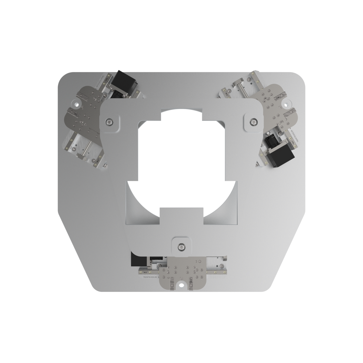
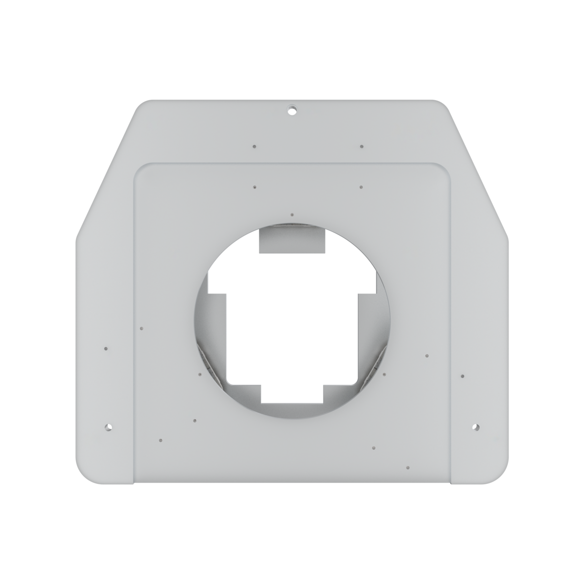
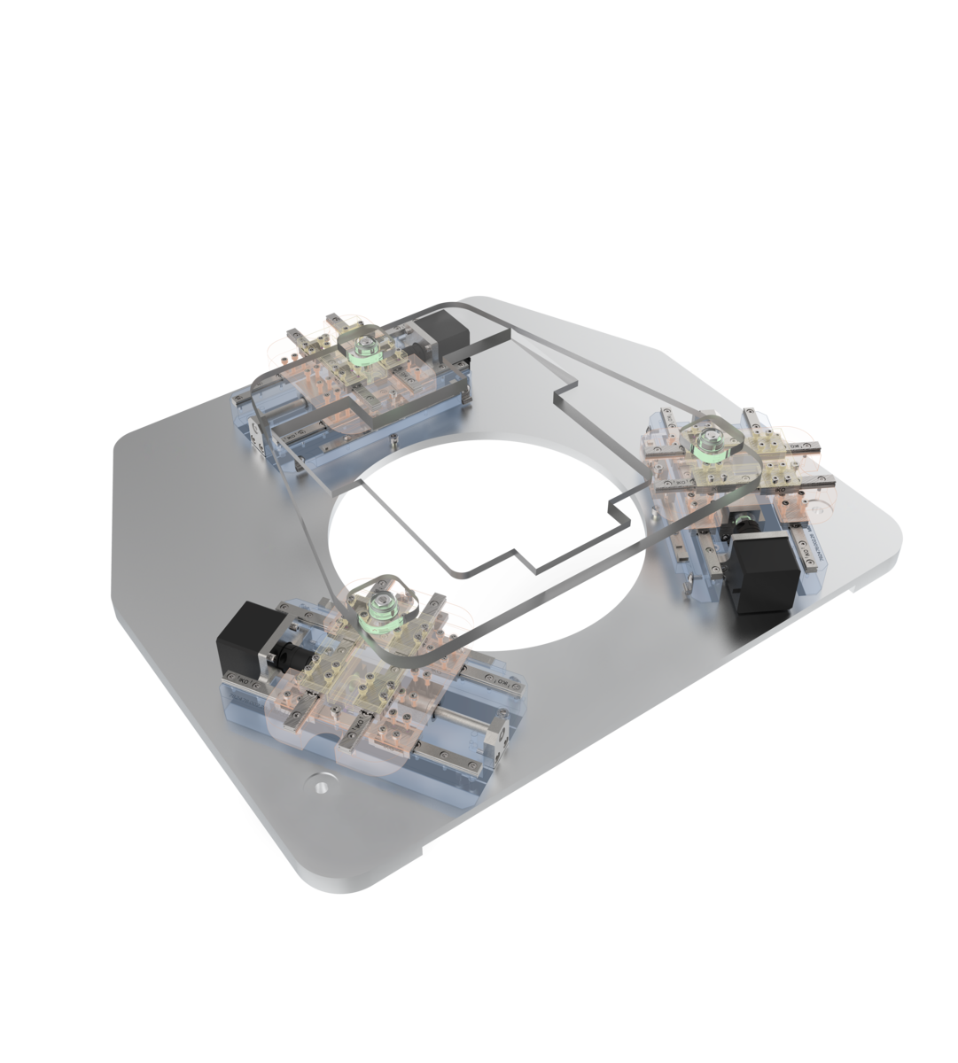
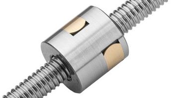
Surface aligner with stepper motor and ball screw
With this aligner, second translational movements of 15 mm in the plane and a rotation around the vertical of up to ± 5 degrees are realized. The motion R (Theta) results from the XY combination. The aligner is designed for loads up to 5 kg. The transmitted light aperture allows transfer measurement.
Outstanding precision in high vacuum
|
|
|
|
|
Options:
|
Individual extensions and customizations
Engineering services include the fitting of the systems to your structure and the desired motion control or the completely individual solution development with 3D design for the application-specific positioning task.
Furthermore, we develop prototypes and like to adapt the systems to the environmental requirements of your application particle emission, radiation, temperature, precision special parts manufacturing, working height, collision protection, safety concept, compensation factor and filter, sensor mounting, brake, decoupling, special lubrication, special colors, holders, adapters, special motors with pharmaceutical approval, comprehensive documentation, test protocoll, llife cycle tests
Fields of application
HV / UHV wafer inspection, semiconductor inspection, semiconductor alignment, alignment of samples at high vacuum, analysis, incident and transmission light measurements, transfer measurements, assembly tasks, alignment of parts before joining
782476:001.26 | X | Y | Rz | |
Standard System |
| LA85 | LA85 | LA85 |
[mm; deg] | ± 15 | ± 15 | ± 5 | |
Repeatability unidirectional | [µm; deg] | ± 0.8 | ± 0.8 | ± 0.8 |
Repeatability bidirectional | [µm; deg] | ± 1 | ± 1 | ± 1 |
[mm/s; deg/s] | 1 | 1 | 1 | |
| Max. speed | [mm/s; deg/s] | 2 | 2 | 2 |
Max. load | [N] | 50 | 50 | 50 |
Motor |
|
| ||
Drive |
| Ball Screw | Ball Screw | |
Feedback | Open Loop | |||
| Aperture | [mm] | 235 | ||
| Length x width x height | [mm] | 545 x 484 x 95 | ||

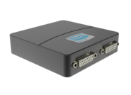
FMC400/450
Multi-axis controller fully ready for tracking, simple creation of own programs.
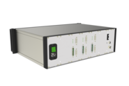
FMC220
Versatile combinable controller, ideal for laboratory applications, control of 1 - 128 axes simultaneously
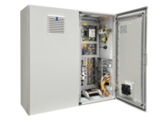
FMC250/280
Multi-axis controller with increased current and voltage for point-to-point positioning.
PLC
We support integration of our systems into PLC architectures, e.g. Beckhoff
ACS
We support integration of our systems into your ACS environment
Used Standard Components
LA85-SM

KGT 1214
Related Products
 | Tripod, Rotary Stage, XY- Stage, Hexapod Alternative | Travel XYZ 30 x 30 x 20 mm, RxRy 4°, Rz 360° - XYZ Tip-Tilt System")

 | travel XYZ 30 x 30 x 20 mm, RxRy 4°, Rz 360° - Inspection and Mikroscopy")
The architecture of a multi-axis system has a significant influence on installation space, dynamics, accuracy, controller requirements, and cost. The rating scale is: +++ low / ++ medium / + high.
| Criterion | Stacked (XY-Z) | Portal (X-YZ) | Gantry (2X-YZ / 2XY-Z) |
|---|---|---|---|
| Installation space (footprint, structural cost) | + | +++ | ++ |
| Natural frequency (stiffness, settling time, sensitivity to external disturbances) | + | ++ | +++ |
| Dynamics (speed, acceleration, cycle time) | + | ++ | +++ |
| Accuracy | + | ++ | +++ |
| Controller requirements (gantry mode, cost) | +++ | +++ | ++ |
| Total cost | +++ | +++ | ++ |
- Stacked: Ideal for compact, cost-efficient systems with high dynamics; limited for very large working areas.
- Portal: A balanced compromise between stiffness, dynamics, and working area; higher mechanical and control effort.
- Gantry: Optimal for large working areas and high planarity requirements; highest complexity, controller requirements, and cost.
In addition to these basic architectures, Steinmeyer Mechatronik also offers compact multi-axis combinations as well as custom-specific solutions—depending on installation space, load, dynamics, and accuracy requirements.
The specifications are based on a right-handed, system-oriented coordinate system. The designation of the axes and degrees of freedom follows the assignment below:
| Degree of freedom | Designation at STM | Description |
|---|---|---|
| Translation X | X | Direction of travel away from the motor or head end |
| Translation Y | Y | Lateral direction of travel |
| Translation Z | Z | Vertical movement opposite to gravity (↑) |
| Rotation about X (Rx) | ω (Omega) | Roll |
| Rotation about Y (Ry) | φ (Phi) | Pitch |
| Rotation about Z (Rz) | θ (Theta) | Yaw |
Is there a standardized coordinate system for axis designation in positioning applications?
Unfortunately not. Especially for rotational degrees of freedom, there is no globally standardized designation, and naming conventions depend strongly on the specific discipline (e.g., mechanics, robotics, aerospace, mechanical engineering, CNC technology, optics).
Below is an overview of how rotational axes (rotational degrees of freedom) are commonly designated, grouped by application area.
1. General mechanical definition (DIN / ISO / robotics / mechatronics)
- Translational axes: X, Y, Z
- Rotational axes:
- Rx – Rotation about the X-axis (→ roll motion)
- Ry – Rotation about the Y-axis (→ pitch motion)
- Rz – Rotation about the Z-axis (→ yaw motion)
This notation is clear, unambiguous, and widely used in mechatronics, robotics, and kinematic analysis.
It is used, for example, in Denavit–Hartenberg parameters, CAD systems (SolidWorks, Creo, Siemens NX), and robot programming languages (KUKA, FANUC, UR).
2. Aerospace / navigation systems (Euler angles)
- Roll (φ) – Rotation about the X-axis
- Pitch (θ) – Rotation about the Y-axis
- Yaw (ψ) – Rotation about the Z-axis
These designations are firmly established when it comes to spatial orientation (e.g., for drones, aircraft, gimbals, cameras).
To add to the confusion, this even involves a left-handed coordinate system. Pilots are well aware that gravity points toward the center of the Earth and therefore define the Z-axis as positive downward.
Mechanical engineers do not find this positive. In their convention, Z points upward.
3. CNC technology / machine tools (DIN 66217, ISO 841)
Here is the conventional machine axis designation:
| Axis | Motion | Description | Example |
| X, Y, Z | Translation | Linear axes | Workpiece movement or tool feed |
| A | Rotation about X | e.g., tilting table, rotary axis | |
| B | Rotation about Y | e.g., swivel head | |
| C | Rotation about Z | e.g., rotary table |
This is the common nomenclature for machining centers, rotary tables, hexapods, etc.
4. Optics / metrology / precision mechatronics
In highly precise positioning systems, the mathematically rigorous notation from kinematics is often preferred:
- Translations: X, Y, Z
- Rotations: θx, θy, θz
or alternatively φx, φy, φz
This notation is advantageous when rotations are specified in the microradian or µrad range (e.g., for wobble, tilt, angular errors).
Yes. Many multi-axis systems are modular in design and can be adapted to changing requirements. From the initial design stage, provisions are made to allow for extensions, reconfiguration, or functional adaptations.
- Integration of additional process heads
- e.g., measurement, inspection, machining, or handling modules
- Replacement or addition of axes and crossbeams
- Expansion of the working area
- Adaptation to new motion profiles
- Adaptation of the system architecture
- Conversion from stacked to portal or gantry structures (application-dependent)
- Mechanical modifications
- Adjustment of travel ranges, load interfaces, or mechanical interfaces
- Optional functional and equipment upgrades
- Encoders, measurement systems, brakes
- Customer-specific surfaces and coatings
- Adaptation to new process or environmental requirements
- Cleanroom or vacuum environments
- Life science, optics, or semiconductor applications
The degree of modularity depends on the specific system architecture, accuracy requirements, and application. In many cases, a subsequent expansion is more economical than a complete redesign.
- Optimized system architecture: selection of suitable architecture types (e.g., stacked, portal, gantry) matched to the application
- Targeted material selection: use of structurally stable materials to minimize vibration effects
- Well-engineered design principles: stiff structures, short force paths, and a symmetrical layout
- High natural frequency: facilitates system tuning and reduces sensitivity to external disturbances
- Result:
- improved dynamics
- higher positioning accuracy
- stable operation even at high accelerations
Almost all atmospheric multi-axis combinations are unanodized with UHV lubrication for residual pressures up to 10-6 mbar and min. cleanroom class ISO 6 - up to ISO class 2 -1 on request - available. Further stages for more demanding environments up to cleanroom class ISO 2, vacuum up to 10E-11 mbar or hard radiation you will find here:
Overview Clean Room & Vacuum Stages Get in touch with our technical consultant
Materials
Steinmeyer Mechatronik GmbH predominantly uses aluminum for the structure of multi-axis positioning systems.
In special cases, steel and titanium (e.g., for non-magnetic systems) are also possible.
The reason: aluminum efficiently dissipates localized heat, allowing the system to quickly reach a thermally stabilized state—an essential prerequisite for stable and highly accurate positioning systems.
The lower stiffness of aluminum compared to steel is compensated for by design measures, such as:
- a slightly increased table height
- the use of hollow profiles
Important: An aluminum beam and a steel beam with identical geometry exhibit the same deflection under their own weight. For special requirements—e.g., non-magnetic applications—titanium versions are also available.
Functional surfaces and coatings
In addition to standard surfaces, numerous customer-specific surface and coating concepts are available.
These are specifically designed to achieve very high cleanroom classes—up to ISO 1–2, depending on the application and process.
To meet demanding process requirements, we develop and qualify application-specific functional coatings, including:
- Nickel coatings
- PTFE & KEPLA® coatings
- Fluorinated lubricants
- Dicronite® / dry-film coatings
- Application-specific coating combinations
In addition, the following options are available:
- anodized (cleaned)
- alternative color anodizing
- bare aluminum, cleaned
- Bilatal
- Nickel
These surfaces are suitable, for example, for high purity requirements, chemical resistance (life science), or process-critical environments.
Why functional coatings are crucial (before → after)
- Standard surface → EUV-compatible surface
- Reflective → non-reflective, minimized stray light
- Limited sliding capability → maximum sliding performance & reduced wear
- Basic protection → chemical & corrosive resistance
- One-size-fits-all → cost-optimized, application-specific performance
Special surfaces are often required for UV / DUV / EUV applications (X-ray or gamma applications on request).
Are you looking for a technical solution for your application?
Get your first 3D Design in a few days:

Katja Weißbach
Consulting
T +49 351 88585-64
E-Mail

Ronald Schulze
Consulting, Project Management & Engineering
T +49 351 88585-67
E-Mail

Francisco Samuel
Consulting &
Project Management
T +49 351 88585-85
E-Mail

Elger Matthes
Consulting, Concepts, Innovation & Engineering
T +49 351 88585-82
E-Mail
Our references