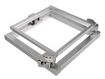
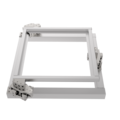
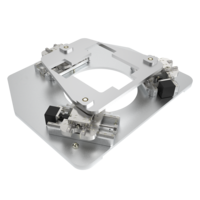
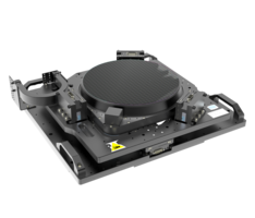
MP700-3 Flat 3D Aligner | XYRz linear motor, air bearing | Aperture 730 mm | Load 28 kg | Travel 5 x 5 mm x 5°
XY Theta Stage
782459:003.26
Parallel kinematic 3D aligner with large aperture
With this aligner, second translational motions of ± 5 mm in the plane and a rotation around the vertical of ± 3° are realized. The motion R (Theta) is the result of the XY combination of axes. The aligner is designed for loads up to 28 kg.
|
|
|
|
|
Options:
|
Individual extensions and customizations
Engineering services include the fitting of the systems to your structure and the desired motion control or the completely individual solution development with 3D design for the application-specific positioning task.
Furthermore, we develop prototypes and like to adapt the systems to the environmental requirements of your application particle emission, radiation, temperature, precision special parts manufacturing, working height, collision protection, safety concept, compensation factor and filter, sensor mounting, brake, decoupling, special lubrication, special colors, holders, adapters, special motors with pharmaceutical approval, comprehensive documentation, test protocoll, llife cycle tests
Fields of application
Positioning of large substrates, masks, frames, screens, printing plates in a low-particle environment, semiconductor printers for applying layer components, UV printers, semiconductor inspection, semiconductor alignment, alignment of samples, analysis, incident and transmitted light measurements, transfer measurements
| 782459:003.26 | X | Y | Rz | |
| Travel | [mm; deg] | ± 5 | ± 5 | ± 3 |
| Repeatability unidirectional | [µm; deg] | ± 0.4 | ± 0.4 | ± 0.0002 |
| Repeatability bidirectional | [µm; deg] | ± 0.7 | ± 0.7 | ± 0.0003 |
| Positioning speed | [mm/s; deg/s] | 50 | 50 | 10 |
| Max. speed | [mm/s; deg/s] | 100 | 100 | 20 |
| Max. Load | [N] | 5 | 5 | 100 |
| Weight | [kg] | 63 | ||
| Length x width x height | [mm] | 990 x 1090 x 225 | ||
| Aperture | 730 x 730 | |||
| Guide | Air Bearing | Air Bearing | Air Bearing | |
| Motor | Ironless Dynamic Linear Motor | Ironless Dynamic Linear Motor | Ironless Dynamic Linear Motor | |
| Feedback | Linear Encoder | Linear Encoder | Linear Encoder | |
| Material | Anodized Aluminum | |||
| Variants clean room | up to clean room class ISO 5 (higher on request) | |||
| Variants beam | UV | |||
| Variants magnetism | magnetic | |||
Related Products
Almost all atmospheric multi-axis combinations are unanodized with UHV lubrication for residual pressures up to 10-6 mbar and min. cleanroom class ISO 6 - or even better - available. Further stages for more demanding environments up to cleanroom class ISO 2, vacuum up to 10E-11 mbar or hard radiation you will find here:
Overview Clean Room & Vacuum Stages Get in touch with our technical consultant
Steinmeyer Mechatronik GmbH mainly uses aluminum for the structure of custom axis combinations, because it efficiently dissipates local heat and quickly reaches a thermally stable state. This is a prerequisite for stable, precise systems. The lower stiffness of aluminum compared to steel is compensated by a slightly higher height of the stages or the use of hollow profiles. Note: An aluminum beam and a steel beam sag equally under their own weight!
In special cases, titanium is also used for magnet-free systems.
What surfaces are available?
Various surface options are available. Depending on the application, anodized and cleaned, alternative colors, aluminum cleaned and bare, bilatal or nickel are available for optimal process suitability (e.g. particularly high degrees of purity, resistance to cleaning with chemicals in the field of life science). Special surfaces are often necessary for UV, DUV or EUV (X-ray, gamma on request).
Depending on the requirements, various drive systems can be used. This can be recognized as an abbreviation in the name below:
- Ground ball screws or lead screws with SM (stepper motor), DC motor or AC servo.
- Electrodynamic linear motors (ironless or iron-core).
- Piezomotors such as Piezo-Legs® or Nanomotion®.
Incremental scales made of steel or Zerodur® or Zeromet® are used as a feedback system in most cases. While this is sufficient for accuracy in the single-digit micrometer range, it makes sense to use interferometric position feedback for accuracy requirements below one micrometer. In systems with “open loop”, i.e. without a measuring system, only precision in the double-digit micrometer range can be achieved; however, due to the simpler controller and the lack of a measuring system, this is the more cost-effective solution.
Are you looking for a technical solution for your application?
Get your first 3D Design in a few days:

Katja Weißbach
Consulting
T +49 351 88585-64
E-Mail

Ronald Schulze
Consulting, Project Management & Engineering
T +49 351 88585-67
E-Mail

Francisco Samuel
Consulting &
Project Management
T +49 351 88585-85
E-Mail

Elger Matthes
Consulting, Concepts, Innovation & Engineering
T +49 351 88585-82
E-Mail
Our references
